NanoVNA + Python = 🖤

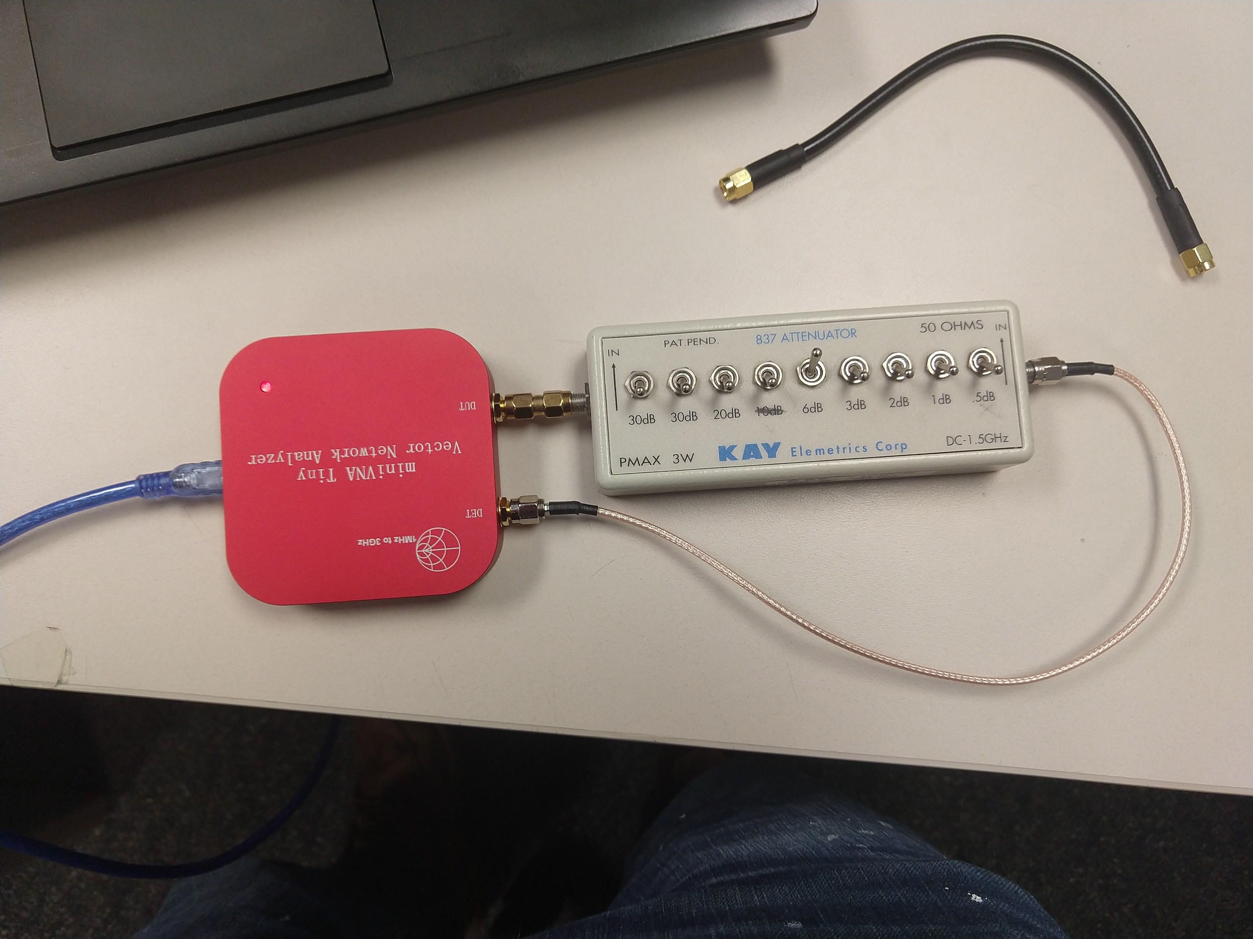
I’ve recently purchased the NanoVNA produced by HCXQS at their store. I’m quite impressed with the product for the price. 50kHz – 4.4GHz T/R Network Analyzer w/ 70dB of dynamic range for S21, and 40dB of dynamic range for S11 measurements for 200.00USD. Th unit is equipped with a touch screen for control and obviously displaying results. In addition, there is a built-in 18650 cell for portable use.

I don’t have much to say about the UI/UX experience because I’ve never used it. The device has the ability to be remotely controlled over a serial interface (through USB). The remote interface offers a large number of points per sweep ( 10,000+, built in UI is limited) and all the niceties of using a modern computer when it comes to display, processing and storage. HCXQS has a program called NanoVNA-Qt to remotely control the unit. There is another program called NanoVNA-Saver, also Qt based but written in Python, with near identical functionality.

Using the documentation supplied by HCXQS and the NanoVNA-Saver repo as a base (except for calibration – I straight up ripped that code from the NanoVNA-Saver repo), I’ve created a small python package for collecting data from the NanoVNA.

Below is an example listing connecting to the unit, loading a calibration file, and performing a measurement.


# script constants 
data_root = Path('../data').resolve()
cal_path = data_root / 'cal'

# get interface
iface = get_interfaces()[0]
iface.open()
vna = NanoVNA_V2_H4(iface)
vna.load_cal(cal_path)
vna.set_sweep(140e6,4.4e9,1001)

# measure 
f, s11, s21 = vna.measure()

Scripting to the Moon

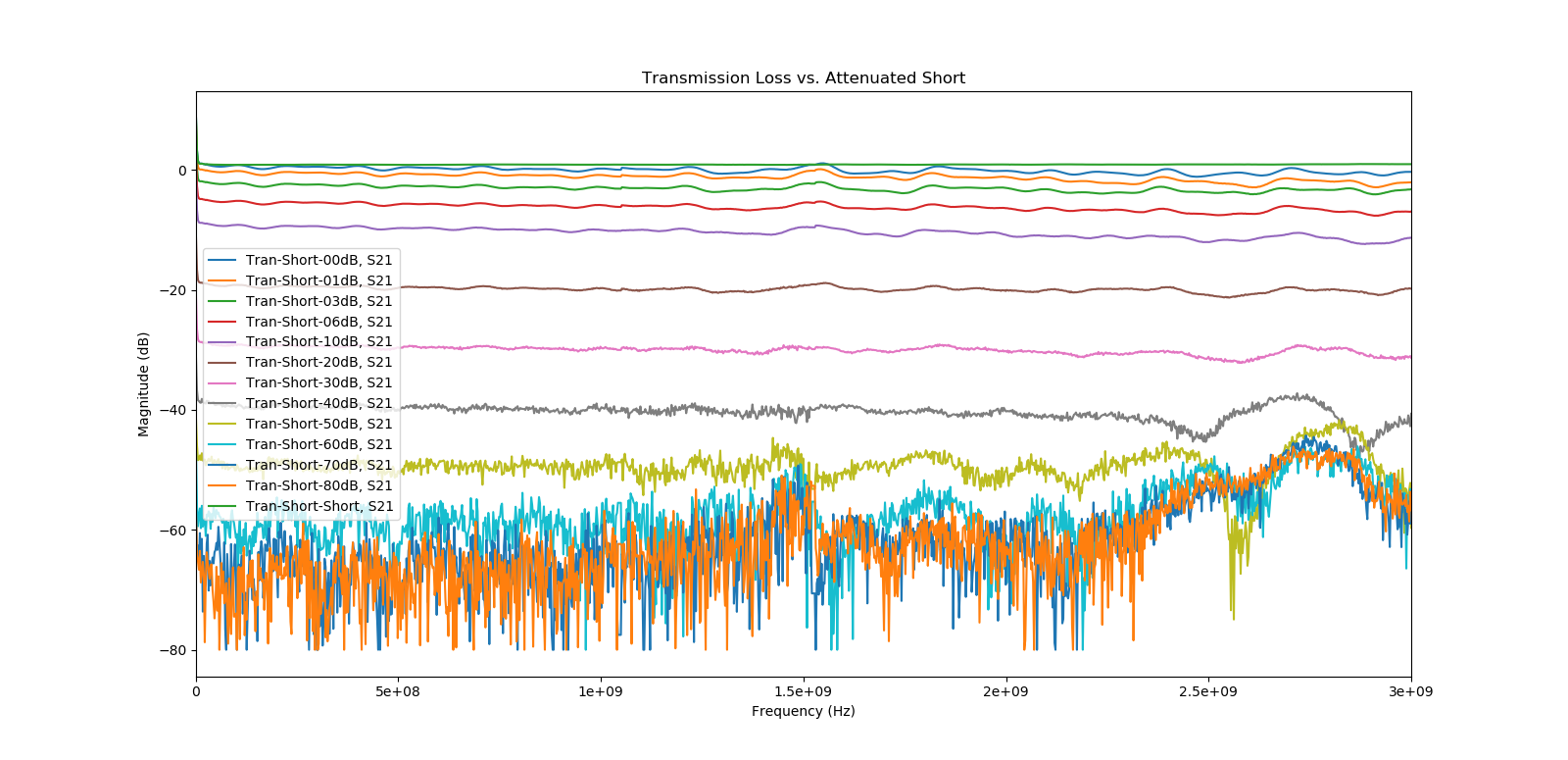
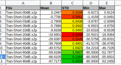
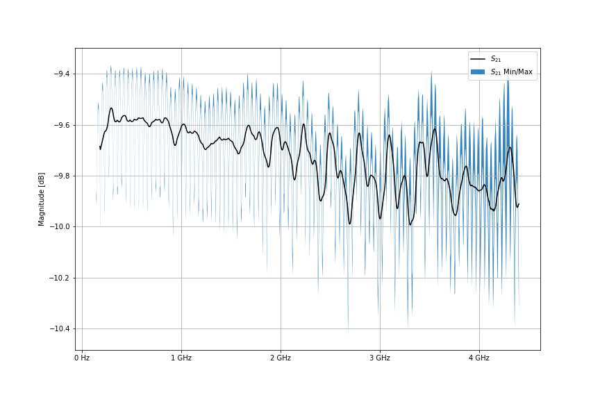
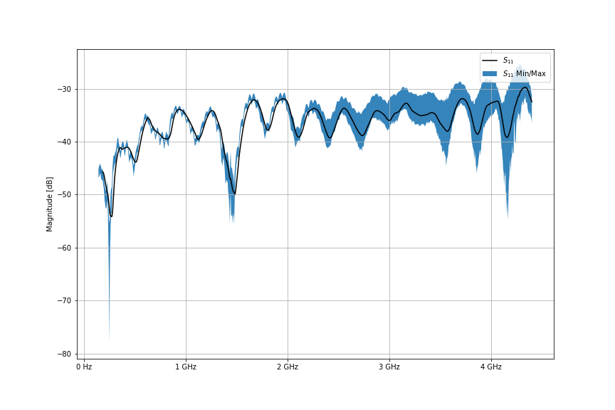
I create a basic script to test my package. The script requests 2,000 sweeps of 1001 points of a NooElec 10dB attenuator. This data is then slightly post-processed and graphed. We can see 0.5 dB of variation across the S21 measurements, and significantly more, (5-7 db), above 3GHz for S11 measurements. It should be noted, we are just above the noise floor (or maybe sitting on it) for these S11 measurements.

S21 of 10dB attenuator from NooElec using the NanoVNA and Python. A Python script commanded the NanoVNA to take 2000 sweeps of 1001 points from 140MHz to 4.4GHz. The plot shows a rolling average of all the data (black) and the min/max values seen over the 2000 sweeps.
S11 of 10dB attenuator from NooElec using the NanoVNA and Python. A Python script commanded the NanoVNA to take 2000 sweeps of 1001 points from 140MHz to 4.4GHz. The plot shows a rolling average of all the data (black) and the min/max values seen over the 2000 sweeps.

Please let me know if you’d find such a package useful. It is currently public on my repository, but it’s bit ‘how you doin’ at this time. I’ll be using this device to collect s-parameters from TI’s CC1200 RF transceiver IC next. TI does not provide optimal matching parameter data for all the operating bands. Therefore, I’m attempting to take manners into my own hands / VNA.

Raspberry Pi Zero W- SSH over USB

If you’re attempting to setup the Zero without Wi-Fi, the best method I’ve found is to utilize Ethernet over USB. This permits SSH over USB. There is quite a few guides illustrating this, but they all assume the host (the computer which you’re connecting the Pi to) will bridge with it’s own internet connection. This gives the Pi access to the router so it will be assigned an IP / register it’s local domain name.

The following steps rehash every other tutorial, but assigns a static IP address to the Pi so you don’t have to worry about bridging.

Modify the config.txt file in the boot parition of the image by adding the following line to the bottom of the file:

dtoverlay=dwc2

Modify cmdline.txt by appending the following after rootwait. Make sure to only use a single space character between settings in the file.

modules-load=dwc2,g_ether

Create a file named ssh to enable sshd on boot.

touch ssh # done! :) 

In the rootfs partition of the image modify /etc/dhcpcd.conf to setup a static IP:

interface usb0

static ip_address=192.168.5.1/24
#static routers=192.168.4.1
#static domain_name_servers=192.168.4.1

Insert your new pre-configured image into your Pi Zero. Wait for a new Ethernet network interface to appear, and manually configure it have an IP address which is on the same subnet as your Pi.

You should now be able to access your device via SSH.

ESP32 – Stock Firmware Disables JTAG

I’ve been working on a project recently with the ESP32.

I purchased 4 raw ESP32-WROOM-32 modules from Digi-key, soldered them to my hardware, and then attempt to flash them over the JTAG interface. Every attempt of programming the module left me with the dreaded all ones seen blah blah blah error.

Error: JTAG scan chain interrogation failed: all ones
Error: Check JTAG interface, timings, target power, etc.
Error: Trying to use configured scan chain anyway...
Error: esp32.cpu0: IR capture error; saw 0x1f not 0x01

All of the existing documentation online suggested a hardware fault so I went into hardware troubleshooting mode until I became fully confident the hardware was not an issue. After much thrashing around, I finally noticed the module were pre-programmed as it was dumping data over the UART port. I managed to re-flash the hardware using the UART interface instead and then the JTAG interface was accessible.

This left me with the following understanding:
1. It’s possible for the firmware to “brick” the JTAG interface
2. ESP32 modules from espressif can potentially come with firmware pre-installed.

I’ve posted to the Espressif Forum here: https://www.esp32.com/viewtopic.php?f=2&t=12600&p=50119#p50119

miniVNA Tiny

I’ve recently been forced to work on an antenna matching issue at work which has been fun and terrifying at the same time (my favorite combination personally). See, I don’t have any traditional RF experience. Everything has been learned on the job / via independent studies; therefore, there I have quite a few gaps I’m trying to fill.

I purchased a miniVNA Tiny to continue my studies at home: http://miniradiosolutions.com/

The miniVNA tiny  runs between $350-$600 dollars which is two to three orders of magnitude less than a traditional professional VNA new or used. That being said, I didn’t expect much. The best part was I didn’t even really know what to expect because I didn’t know what was important :).  I thought measuring the reflected power on a few antennas I had laying around would interest people.

VNA Comparison

At work we have an Agilent E5071C (running Windows XP) with the ECalibration kit (yaas). The green traces are the miniVNA and blue is the Agilent device.

The first two antennas are monopoles which came with a RTL-SDR based SDR. I’m guessing they’re aircraft bands? The measurements between the two VNAs are quite close. The antenna base is a mag-mount which I placed on the most hearty ground plane I could find.  This was my most repeatable test. These sweeps are from 100MHz to 1.2GHz The other tests have the antenna support via a cardboard box sitting on top of the same ground plane. They consist of sweeps from 100MHz to 3GHz.

miniVNA-vs-Agilent-02.jpg
VNA Comparison #1

I don’t like the squiggles in the miniVNA measurement. I’m not sure what the cause is or what to call them? Increasing the calibration points in the range of measurement did not seem to improve the measurement. I believe the Agilent’s output power is higher, but I didn’t see a difference in measurements when I dropped it to -20dBm. I believe whatever these squiggles are the difference in the pass regions.

[Update]: The squiggles are entirely related to the calibration setup. The antennas supplied with a fixed coaxial cable which is huge no-no when performing VNA measurements unless the cable itself it attached during the calibration.

miniVNA-vs-Agilent-01.jpg
VNA Comparison #2

The next two antennas are in the 900MHz / ISM band. I believe their results are quite respectable. You can see a spike around 1.5GHz. It was impossible to remove this with calibration and averaging. It’s advertised the dynamic range of the miniVNA is suppose to be 50dB at 500MHz. I would like to know how to measure the dynamic range for it’s entire operating range so I could estimate if my intended measurement is impossible.

miniVNA-vs-Agilent-04.jpg
VNA Comparison #3

The forth comparison is quite different. It’s likely my fault as this was quite an ad-hoc setup and performed on my lunch break.

miniVNA-vs-Agilent-03.jpg
VNA Comparison #4

Dynamic Range Testing

I put 10 seconds of thought into how I could measure the dynamic range of the miniVNA when measuring transmission or reflected powered, and I thought I figured it out. I decided I would use a variable RF attenuator.

For the transmission measurement, the RF attenuator was placed between the DUT and the DET ports.  The lost should be equal to the set RF attenuator and remain flat across the spec’d range for the attenuator (so I assumed). The attenuator I was using was spec’d from DC to 1.5GHz.


IMG_20190306_132857829
Transmission Loss Test

Luckily, I was right for once. The plot’s legend lists the amount of attenuation selected in dB. The x-axis is frequency, and the y-axis is power measured at the DET port. The following tables shows some basic statistics from 1MHz to 1.5GHz. There appeared to be a constant 0.3 to 0.24 dB error.

Transmission_Test.png
Transmission Loss Plotted

Screenshot from 2019-03-09 16-22-23
Tabulation of mean, standard deviation, min and max of the transmission loss measurements. These measurements range from 1MHz to 1.5GHz.


IdeasX Alpha Manual

I’ve been working hard to make IdeasX deployable for testing in a real world environment. I’ve also be cleaning up the code based to make it easier for others to hopefully join in on the fun. Attached is the user-manual for the IdeasX Alpha.

If you believe you’d be interested in helping or have potential users please don’t be afraid to contact me.

Demo Video:

I say “ummm” five million times. You’ve been warned.