The M17 Project has been hunting for a simple one chip solution for their protocol. If you’re unaware of the M17 project, I’ll briefly summarize it, but I recommend you review their website / join their Discord/IRC/Matrix. M17 is an open source protocol for digital mobile radio (DMR). It’s currently utilizing the Codec2 voice codec for compression of voice. The protocol has support raw data frames as well.
The PHY for M17 is RRC filtered 4-FSK.
Information bits
Symbol
4FSK deviation
Bit 1
Bit 0
0
1
+3
+2.4 kHz
0
0
+1
+0.8 kHz
1
0
-1
-0.8 kHz
1
1
-3
-2.4 kHz
Table from the M17 specification.
The signal is designed to fit within 9kHz of bandwidth for support with analog radios and the standard 12.5kHz channel spacing.
While there is a number of integrated transceivers which support 4-FSK, but there is very few which support RRC. The M17 Team was pursuing the AX5043 based on the amazing work of NotBlackMagic. I recommend they also pursue the CC1200 as it supports M-Ary FM transmissions and reception.
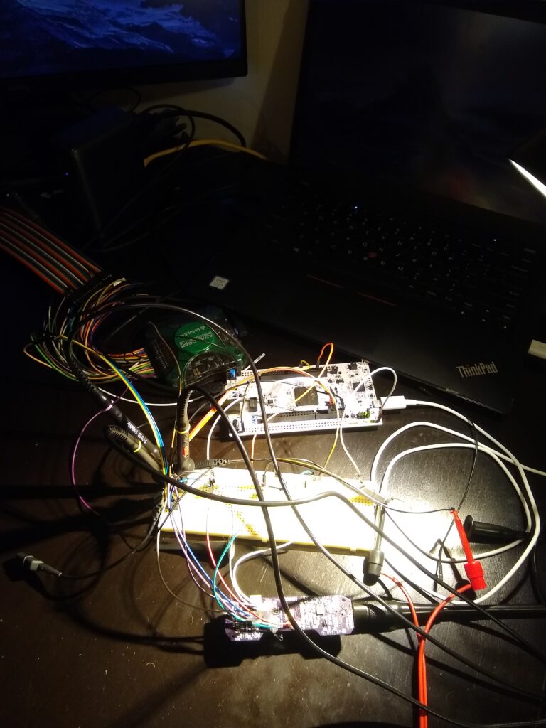
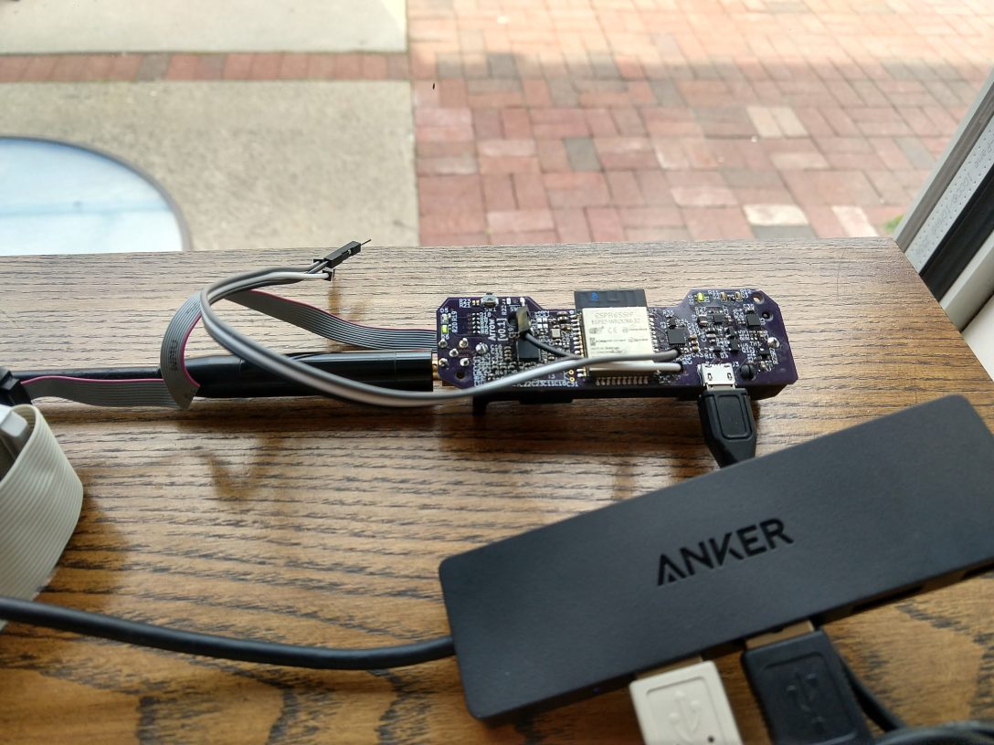
I’m using a STM32 development board strapped to a hacked up Arrow PCBA. The STM32 samples the CFM registers from the CC1200 and dumps the data over USB.
You hear example audio taken from the CC1200 below. Be careful if you’re wearing headphones as there is a bit of static.
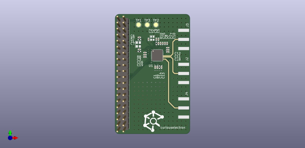
In a quest to measure the input impedance of the CC1200’s LNA in the 2m amatuer radio band, I created a basic development board for the CC1200. The data lines were broken out to a raspberry-pi header, and the RF lines were routed out to edge mount SMA connectors via 50Ohm microstrip. The stackup was JLC2313.
Render of CC1200 Development Board.
This design had a number of issues.
JLCPCB offers a calculator which accounts the soldermask. I didn’t use this tool and instead used KiCad’s built-in calculator which doesn’t account for soldermask. To eliminate this variable, I removed solder mask from the RF traces. This is a common practice, but in the future I should make sure to keep soldermask within the courtyard of the CC1200.
I designed the microstrip to use the 7XXX stackup offered by JLCPCB and not 2313 :D, opps.
The PA and LNA traces are different lengths! This means in order to de-embedded the measurements, I need to calculate the phase-delay for each length (assuming the microstrip is actually 50Ohms…it wasn’t) or perform additional measurements to de-embedded.
The SMA footprint is poorly matched, but to be frank – I wasn’t completely sure of this at this time.
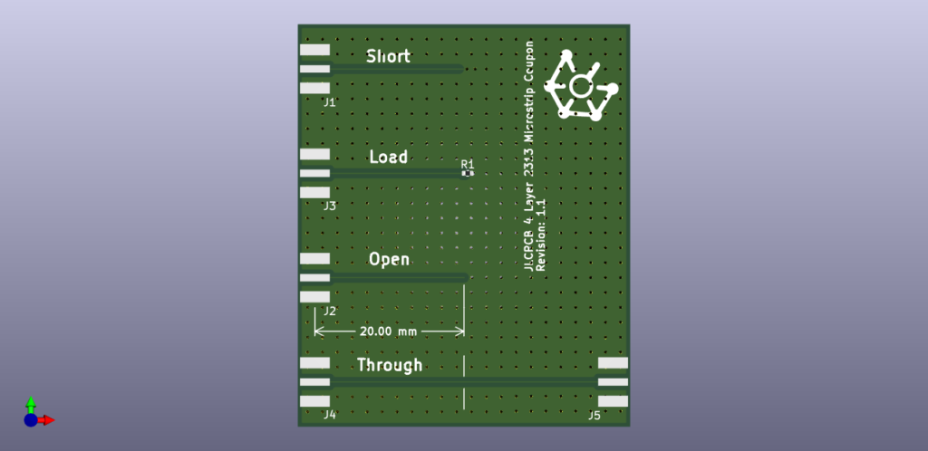
In light of all these issues, I decided to run back to basics and create a basic coupon based on the JLC2313 stackup using the JLCPCB calculator. The coupon was designed to used as a SOL cal standard for de-embedding a 20mm microstrip trace. A 40mm microstrip through connection was also added to quickly confirm the performance of the stackup.
Render of SOL calibration standard for 20mm microstrip de-embedding.
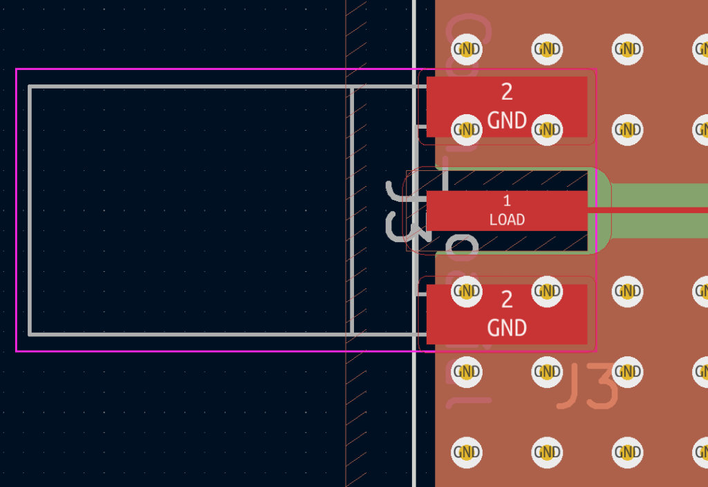
Lastly, after reading a few papers on proper signal launch and reviewing data from the defunked CC1200 development board, I decided to order two versions of the coupon with different versions of the SMA footprint. Both are optimized to have the smallest possible center pin pad, but version v1.0 has ground underneath the center pin, and version v1.1 has a keepout for all copper under the center pin.
Close up of SMA footprint with ground removed from center pin.
Removal of copper under the center pin was critical to achieving an excellent match. The data below was collected using the NanoVNA V2.4 using the curiousmeasurements python package.
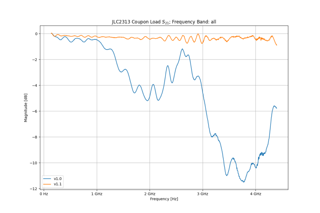
S11 and S21 Measurements from v1.0 (no keepout) and v1.1 (keepout under center pin) revisions.
Version v1.0’s match is unusable above 1GHz, while v1.1 has a return loss <-10dB all the way to 4.4GHz. Not bad for some no-name Amazon SMA connectors…
The same continues for transfer response. The performance is excellent for v1.1. I was quite surprised how much such a small change drastically improved performance.
I’ve recently purchased the NanoVNA produced by HCXQS at their store. I’m quite impressed with the product for the price. 50kHz – 4.4GHz T/R Network Analyzer w/ 70dB of dynamic range for S21, and 40dB of dynamic range for S11 measurements for 200.00USD. Th unit is equipped with a touch screen for control and obviously displaying results. In addition, there is a built-in 18650 cell for portable use.
I don’t have much to say about the UI/UX experience because I’ve never used it. The device has the ability to be remotely controlled over a serial interface (through USB). The remote interface offers a large number of points per sweep ( 10,000+, built in UI is limited) and all the niceties of using a modern computer when it comes to display, processing and storage. HCXQS has a program called NanoVNA-Qt to remotely control the unit. There is another program called NanoVNA-Saver, also Qt based but written in Python, with near identical functionality.
Using the documentation supplied by HCXQS and the NanoVNA-Saver repo as a base (except for calibration – I straight up ripped that code from the NanoVNA-Saver repo), I’ve created a small python package for collecting data from the NanoVNA.
Below is an example listing connecting to the unit, loading a calibration file, and performing a measurement.
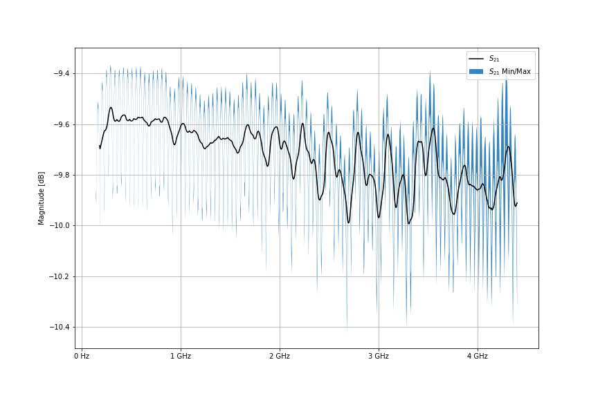
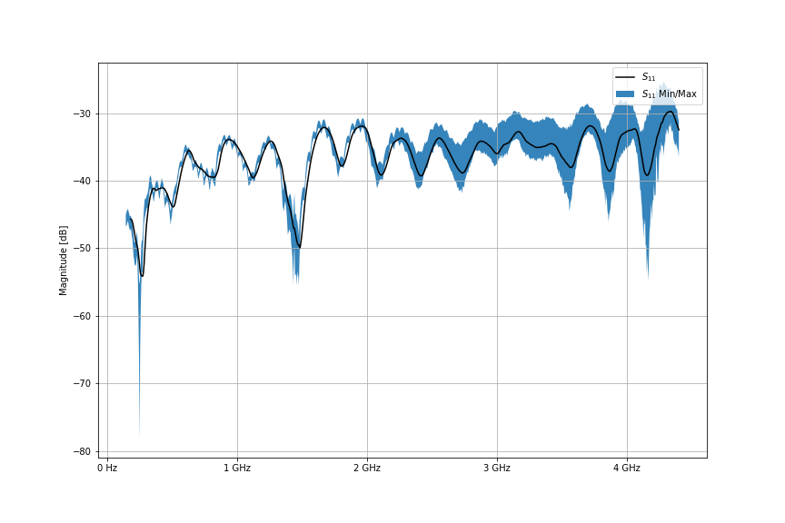
I create a basic script to test my package. The script requests 2,000 sweeps of 1001 points of a NooElec 10dB attenuator. This data is then slightly post-processed and graphed. We can see 0.5 dB of variation across the S21 measurements, and significantly more, (5-7 db), above 3GHz for S11 measurements. It should be noted, we are just above the noise floor (or maybe sitting on it) for these S11 measurements.
S21 of 10dB attenuator from NooElec using the NanoVNA and Python. A Python script commanded the NanoVNA to take 2000 sweeps of 1001 points from 140MHz to 4.4GHz. The plot shows a rolling average of all the data (black) and the min/max values seen over the 2000 sweeps. S11 of 10dB attenuator from NooElec using the NanoVNA and Python. A Python script commanded the NanoVNA to take 2000 sweeps of 1001 points from 140MHz to 4.4GHz. The plot shows a rolling average of all the data (black) and the min/max values seen over the 2000 sweeps.
Please let me know if you’d find such a package useful. It is currently public on my repository, but it’s bit ‘how you doin’ at this time. I’ll be using this device to collect s-parameters from TI’s CC1200 RF transceiver IC next. TI does not provide optimal matching parameter data for all the operating bands. Therefore, I’m attempting to take manners into my own hands / VNA.
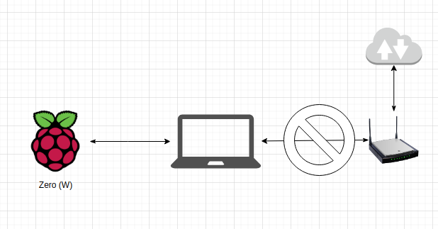
If you’re attempting to setup the Zero without Wi-Fi, the best method I’ve found is to utilize Ethernet over USB. This permits SSH over USB. There is quite a few guides illustrating this, but they all assume the host (the computer which you’re connecting the Pi to) will bridge with it’s own internet connection. This gives the Pi access to the router so it will be assigned an IP / register it’s local domain name.
The following steps rehash every other tutorial, but assigns a static IP address to the Pi so you don’t have to worry about bridging.
Modify the config.txt file in the boot parition of the image by adding the following line to the bottom of the file:
dtoverlay=dwc2
Modify cmdline.txt by appending the following after rootwait. Make sure to only use a single space character between settings in the file.
modules-load=dwc2,g_ether
Create a file named ssh to enable sshd on boot.
touch ssh # done! :)
In the rootfs partition of the image modify /etc/dhcpcd.conf to setup a static IP:
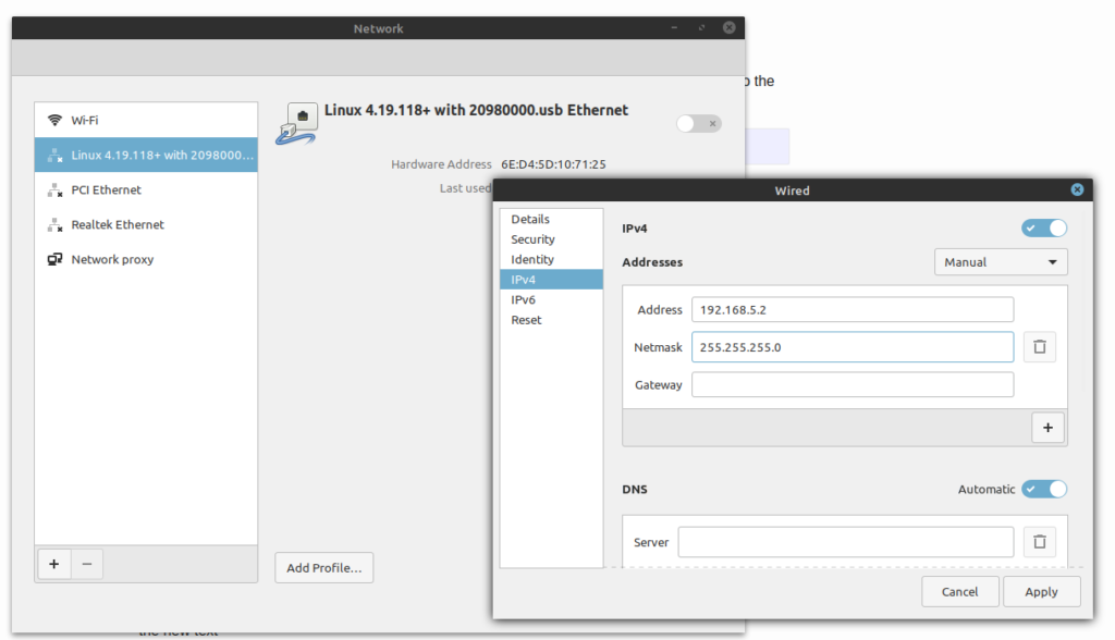
Insert your new pre-configured image into your Pi Zero. Wait for a new Ethernet network interface to appear, and manually configure it have an IP address which is on the same subnet as your Pi.
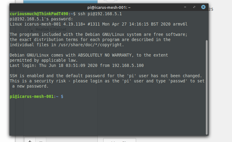
You should now be able to access your device via SSH.
I’ve been working on Arrow for a while now, but I think it’s time I put it to rest for a bit and write down what has been completed.
I’ve learned lots of fun things from this project (and some horrible things…like AX.25 and the FCC limitations on the 2M band’s data rates!) and I hope someone in the future can make use of it or would be willing to work with me to encourage further development!
What is It?
Currently, Arrow is a full fledged TNC which means the following KISS parameters are supported: TX Delay, TX Tail (why is this even a thiiiiing?!?), Slot Time, and Persistence with built-in BLE connectivity and a 2M radio which is frequency agile. In addition to AFSK for AX.25, the radio supports FSK, GFSK, MFSK, and OOK along with M-ary options.
What is a TNC?
TNC for the uninformed stands for Terminal Node Controller in the amateur radio space….Yeah, I didn’t get much from that the first time I heard it either. In fact, I still don’t. I recommend reading the Wikipedia page for a primer.
In short, a TNC is a modem which was used in the early days of packet radio (actually lives on today mainly in APRS) to send digital data from your computer over audio links. TNCs were fantastic because they allow anyone with a radio capable of sending audio (the most common kind when TNCs were all the rage) to send digital data. You can think of it as the cooler cousin of your 56K dial-up modem, but typically way slower.
TNCs were originally used around about the same time the internet was in it’s infancy. The infrastructure and cost at the time for the internet was substantial; so instead amateur hobbyists would setup internet-like networks using what amounts to their walkie talkies, their home computer, and I hope you can guess it at this point – yes, their TNC.
Why did I do it?
I want to explore and eventually create a new standard for packet radio in the Amatuer space which could provide voice, and data. While I’m still far from the dream I knew the solution would need the following:
Use modern digital modulation techniques for better BER at low SNR.
Reverse compatibility or support of AX.25 for APRS.
Cheap to drive adoption
Built-In Radio and Frequency agile
Current Specifications and Capabilities
Hardware
TI (CC1200) RF Transceiver IC with Balun + Matching Network for 2M (no PA at the moment)
ESP32
18650 cell w/ built-in charger
Micro-USB connection for charging and UART access for debugging
JTAG port
Status LEDs
TX
RX
Battery Charging
Battery Charged
Capabilities
Arrow uses the KISS protocol over the Bluetooth SPP profile. This means when Arrow is connected to a computer, tablet or phone it presents itself as a virtual serial port. The KISS protocol is one of the standardized methods used to communicate and configure TNCs; therefore, it is well supported by existing programs (LinBPQ), apps (APRSDroid), and kissattach (Linux’s ax25-tools).
The uC on-board (ESP32) directly samples data from the CC1200 to decode FM AFSK BELL202 utilized for the standard 1200bps AX.25 used for APRS. Here you can see a video using two arrows to send a ping request over AX.25.
This combination provides what amounts to a plug-and-play solution for linking Arrow into existing Amatuer Radio solutions. The combination does have some limitations I hope to address (see below), but I believe hits most of my goals listed above.
Limitations
The current implementation has the following limitations:
The CC1200 does not support LoRa or PSK.
The output power is very low (+15dBm) and a PA must be added for this to be viable solutions. Please reach out to me if you’re willing to help.
Bluetooth SPP is not supported by iOS, but luckily the code can be adjusted to use a BLE GATT/GAP setup instead.
Learn More
Here is a presentation I’ve done on Arrow
Where can I get one?
I don’t believe the current solution is viable with its low output power. It does work well as an APRS receiver. If you’re interested in purchasing one feel free to contact me via this forum. The code and electrical design files can be found here. Hack away.
I’ve been working on a project recently with the ESP32.
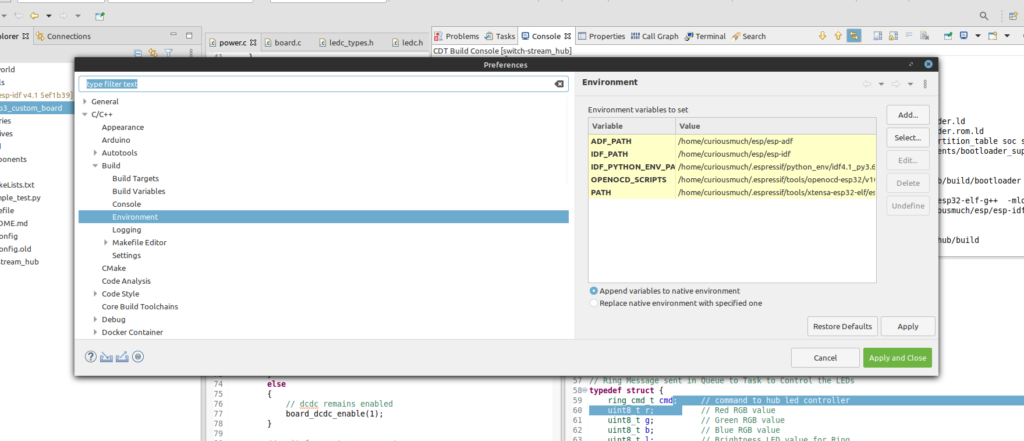
I purchased 4 raw ESP32-WROOM-32 modules from Digi-key, soldered them to my hardware, and then attempt to flash them over the JTAG interface. Every attempt of programming the module left me with the dreaded all ones seen blah blah blah error.
Error: JTAG scan chain interrogation failed: all ones
Error: Check JTAG interface, timings, target power, etc.
Error: Trying to use configured scan chain anyway...
Error: esp32.cpu0: IR capture error; saw 0x1f not 0x01
All of the existing documentation online suggested a hardware fault so I went into hardware troubleshooting mode until I became fully confident the hardware was not an issue. After much thrashing around, I finally noticed the module were pre-programmed as it was dumping data over the UART port. I managed to re-flash the hardware using the UART interface instead and then the JTAG interface was accessible.
This left me with the following understanding: 1. It’s possible for the firmware to “brick” the JTAG interface 2. ESP32 modules from espressif can potentially come with firmware pre-installed.
I’ve recently been forced to work on an antenna matching issue at work which has been fun and terrifying at the same time (my favorite combination personally). See, I don’t have any traditional RF experience. Everything has been learned on the job / via independent studies; therefore, there I have quite a few gaps I’m trying to fill.
The miniVNA tiny runs between $350-$600 dollars which is two to three orders of magnitude less than a traditional professional VNA new or used. That being said, I didn’t expect much. The best part was I didn’t even really know what to expect because I didn’t know what was important :). I thought measuring the reflected power on a few antennas I had laying around would interest people.
VNA Comparison
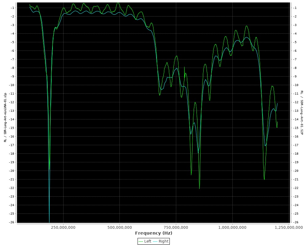
At work we have an Agilent E5071C (running Windows XP) with the ECalibration kit (yaas). The green traces are the miniVNA and blue is the Agilent device.
The first two antennas are monopoles which came with a RTL-SDR based SDR. I’m guessing they’re aircraft bands? The measurements between the two VNAs are quite close. The antenna base is a mag-mount which I placed on the most hearty ground plane I could find. This was my most repeatable test. These sweeps are from 100MHz to 1.2GHz The other tests have the antenna support via a cardboard box sitting on top of the same ground plane. They consist of sweeps from 100MHz to 3GHz.
VNA Comparison #1
I don’t like the squiggles in the miniVNA measurement. I’m not sure what the cause is or what to call them? Increasing the calibration points in the range of measurement did not seem to improve the measurement. I believe the Agilent’s output power is higher, but I didn’t see a difference in measurements when I dropped it to -20dBm. I believe whatever these squiggles are the difference in the pass regions.
[Update]: The squiggles are entirely related to the calibration setup. The antennas supplied with a fixed coaxial cable which is huge no-no when performing VNA measurements unless the cable itself it attached during the calibration.
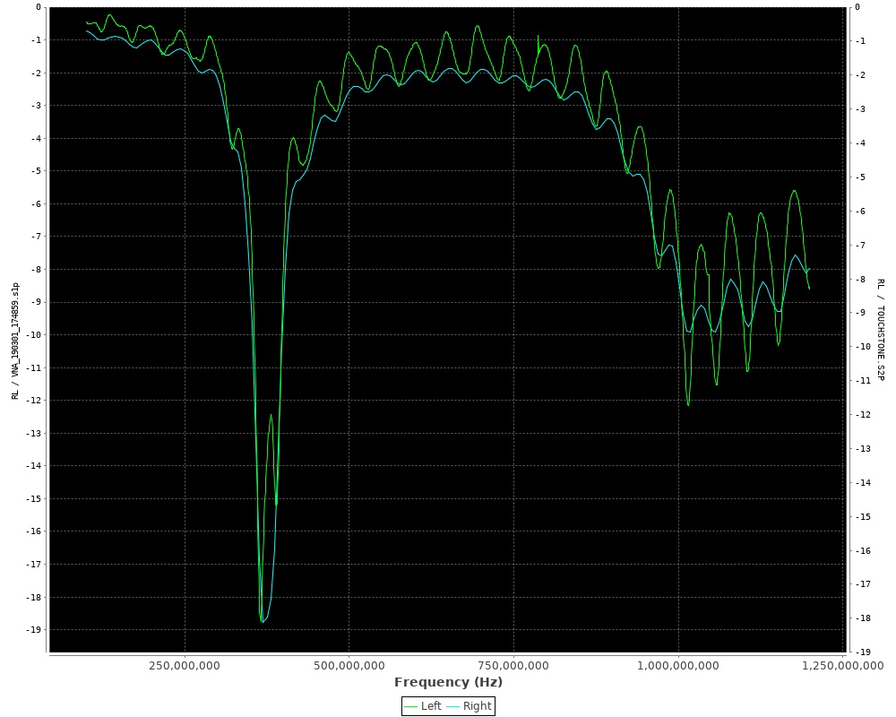
VNA Comparison #2
The next two antennas are in the 900MHz / ISM band. I believe their results are quite respectable. You can see a spike around 1.5GHz. It was impossible to remove this with calibration and averaging. It’s advertised the dynamic range of the miniVNA is suppose to be 50dB at 500MHz. I would like to know how to measure the dynamic range for it’s entire operating range so I could estimate if my intended measurement is impossible.
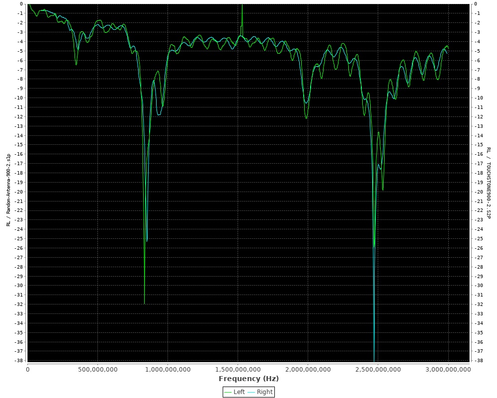
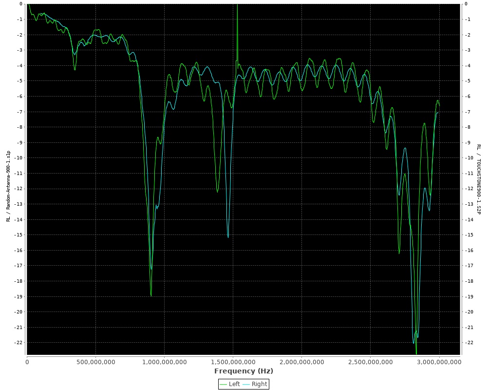
VNA Comparison #3
The forth comparison is quite different. It’s likely my fault as this was quite an ad-hoc setup and performed on my lunch break.
VNA Comparison #4
Dynamic Range Testing
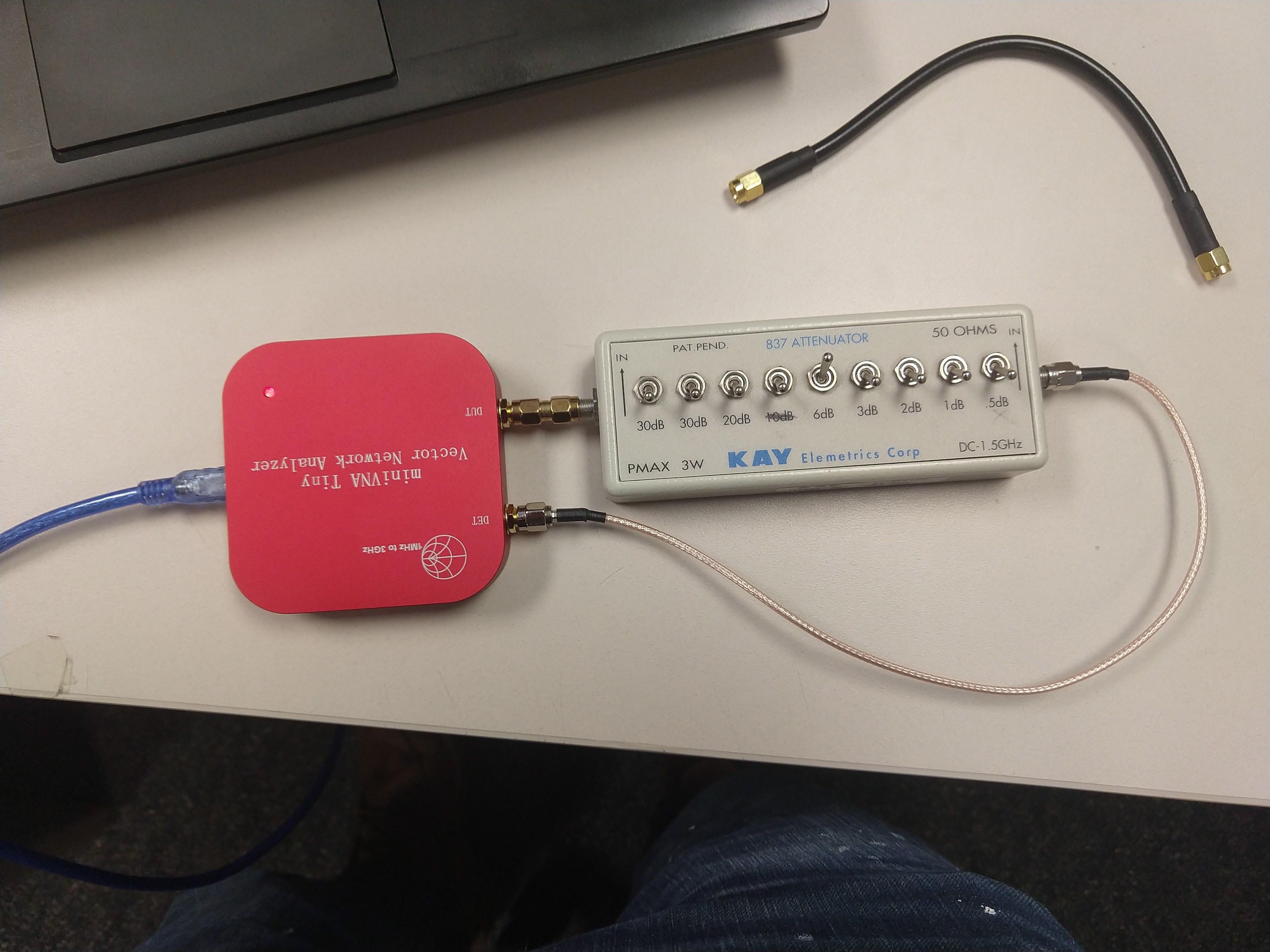
I put 10 seconds of thought into how I could measure the dynamic range of the miniVNA when measuring transmission or reflected powered, and I thought I figured it out. I decided I would use a variable RF attenuator.
For the transmission measurement, the RF attenuator was placed between the DUT and the DET ports. The lost should be equal to the set RF attenuator and remain flat across the spec’d range for the attenuator (so I assumed). The attenuator I was using was spec’d from DC to 1.5GHz.
Transmission Loss Test
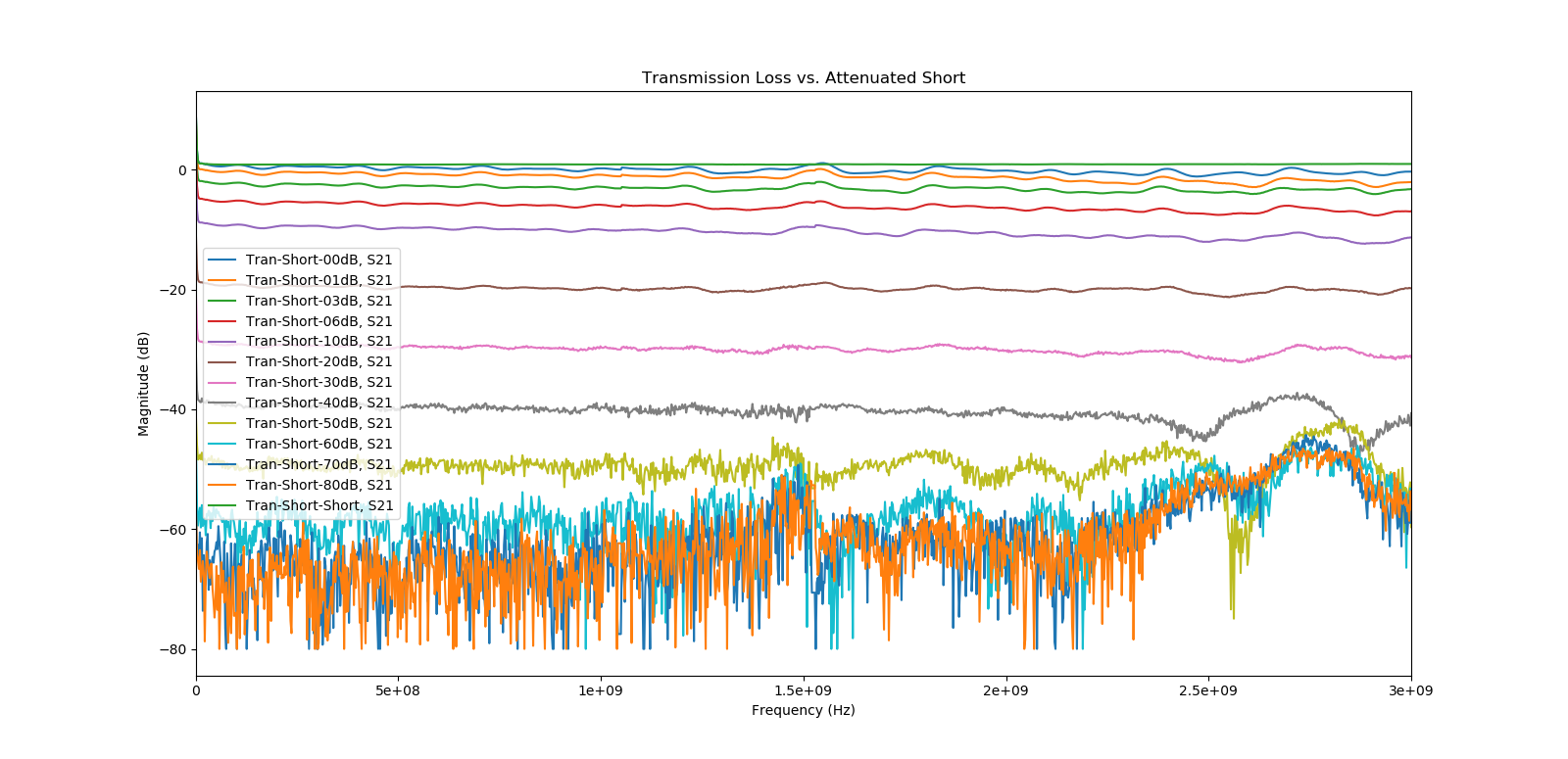
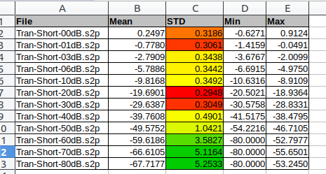
Luckily, I was right for once. The plot’s legend lists the amount of attenuation selected in dB. The x-axis is frequency, and the y-axis is power measured at the DET port. The following tables shows some basic statistics from 1MHz to 1.5GHz. There appeared to be a constant 0.3 to 0.24 dB error.
Transmission Loss Plotted
Tabulation of mean, standard deviation, min and max of the transmission loss measurements. These measurements range from 1MHz to 1.5GHz.
I’ve been working hard to make IdeasX deployable for testing in a real world environment. I’ve also be cleaning up the code based to make it easier for others to hopefully join in on the fun. Attached is the user-manual for the IdeasX Alpha.
If you believe you’d be interested in helping or have potential users please don’t be afraid to contact me.
Demo Video:
I say “ummm” five million times. You’ve been warned.
This is old material generated around 2016-2017. I’m posting here to archive the material.
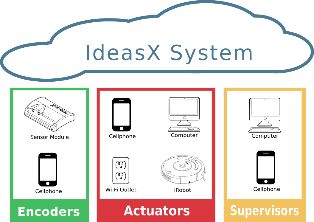
The IdeasX system consists of 3 categories of devices:
A few examples of the devices types in the IdeasX system.
Encoder – Encoders are sensor equipped devices designed to interpret any feedback an individual can provide with the disability. A few examples of feedback is limb movement, EMG, EEG, and respiration. As a device which will basically “live” with the user, encoders need to be light, portable, wireless, and have a long battery life. In addition, change is hard so encoders have to be a breeze to configure and setup.
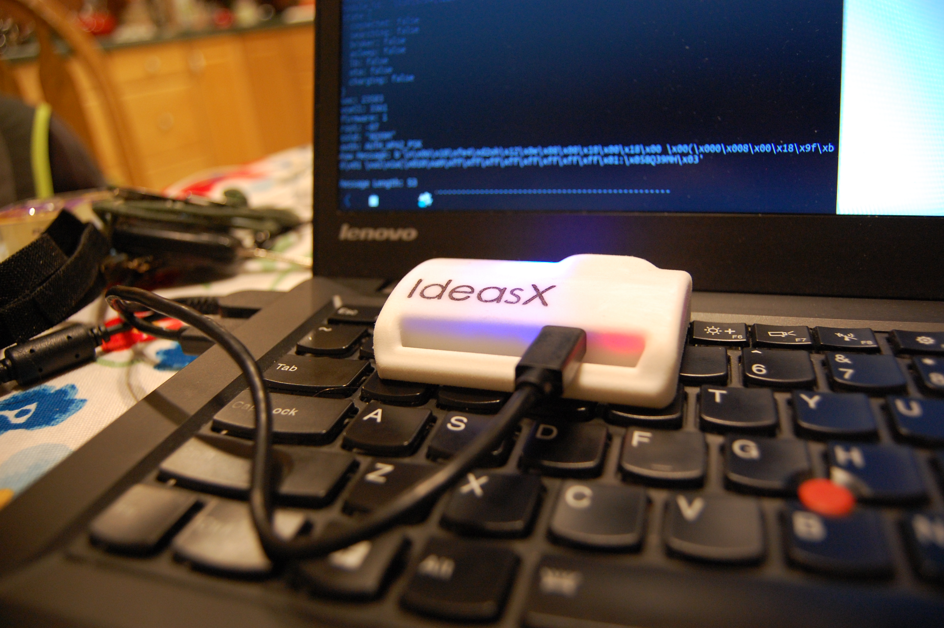
Current development state of a custom Wi-Fi based encoder aptly named “the module.” The device is charging denoted by the red light, and connected to the system denoted by the pulsating blue light.
Current development is focusing on detecting limb movement through the industry standard sensing method (gigantic switches, seriously), and a 3 axis accelerometer / 3 axis gyroscope IMU. IMU stands for inertial measurement unit. The information detected by the encoders is then processed locally and or streamed directly to the IdeasX system through Wi-Fi. Future devices may utilize lower power technology such as 802.15 or BLE.
Actuator – Actuators are devices which can be controlled by encoders. Actuators can be any device which can connect to the IdeasX system and has a list of commands for actuating that device. (Yes, you can make an encoder an actuator.)
There is quite a few actuators underdevelopment.
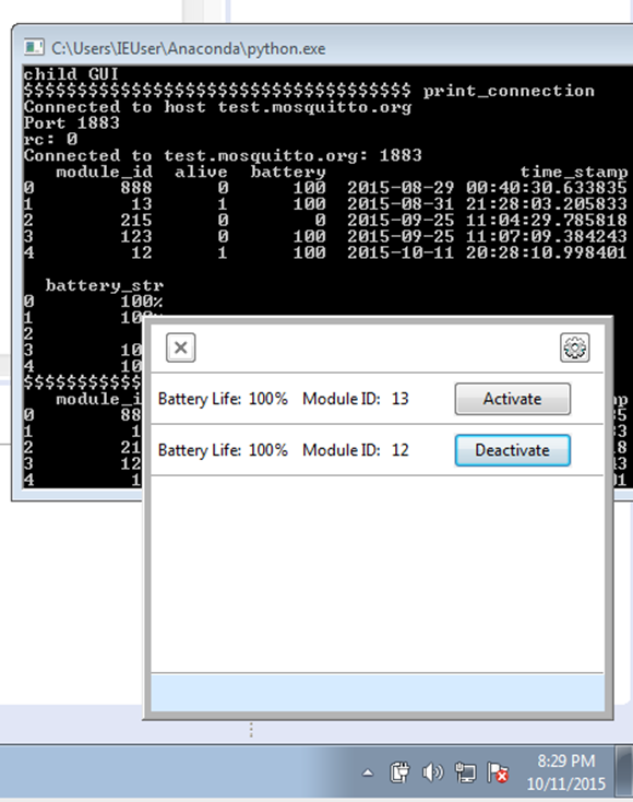
Workstation Client – A piece of software which allows encoders to send keystrokes, touches, and mouse clicks to any computer / smart device installed. It is specifically designed to interface with existing accessibility software. It also provides dialogs for automated pairing of encoders and actuators, lists of the active encoders in an institution / network, and dialogs for configuring encoders in the network.
iRobot – The iRobot Roomba is an amazing piece of technology which can do a lot more good than just cleaning your floors! iRobot provides a low-cost robotics platform called the Create based on the latest commercial Roomba. The Create provides access to the robot’s sensors and routines through a interface port. Undergraduate Temple students are currently designing a low-cost, plug and play kit which enables the Create to connect to the IdeasX system permitting the robot to be remotely controlled. This will provide opportunities to chair bounded students and users to interact spatially in the world.
Wi-Fi Outlet – One powerful teaching tool utilized by therapists is called the Power Link 4 which is basically an adjustable relay. The Power Link allows a binary sensor to active a wall-powered device. The Power Link can be setup to be latching, or latched for a period of time. The tool is often used to help formulate a cause and reaction relationship between the sensor and world for the user (Hey! I pressed this and this wall lamp turned on? This is cool.) Unfortunately, despite being a rather simplistic device the Power Link retails for over 200 US dollars. Luckily, for IdeasX there is already an abundance of devices which can emulate the role of the Power Link and more, are cheaper, and the only thing that stands in way is software!
Supervisor – Supervisors are devices loaded with management software for the IdeasX system. The software can exist as an app for smart devices, a web interface, or a native application of OSX, Windows and Linux. The role of software is to permit therapist to configure every aspect of the system and the devices in it.
Briefly, the purpose of the Supervisors include the following:
Listing active Encoders and Actuators in the IdeasX System
Pairing Encoders with Actuators
Storing Wi-Fi and Network parameters in Encoders and Actuators
Modification of Encoder sensitivity and Actuator functionality
Configuring Encoders for gesture recognition
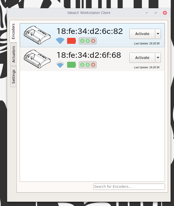
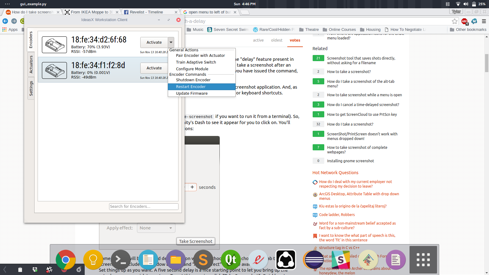
Development thus far was originally a WX application for the Workstation Client. We were on a horrible deadline and the developer really worked magic to make it happen.
Okay. Okay. You can laugh, but what we did was pretty amazing for our original timeline.
I’ve recently been porting this to Qt which, if I may say so myself, looks amazingly less horrible, but still a bit horrible.