The M17 Project has been hunting for a simple one chip solution for their protocol. If you’re unaware of the M17 project, I’ll briefly summarize it, but I recommend you review their website / join their Discord/IRC/Matrix. M17 is an open source protocol for digital mobile radio (DMR). It’s currently utilizing the Codec2 voice codec for compression of voice. The protocol has support raw data frames as well.
The PHY for M17 is RRC filtered 4-FSK.
Information bits
Symbol
4FSK deviation
Bit 1
Bit 0
0
1
+3
+2.4 kHz
0
0
+1
+0.8 kHz
1
0
-1
-0.8 kHz
1
1
-3
-2.4 kHz
Table from the M17 specification.
The signal is designed to fit within 9kHz of bandwidth for support with analog radios and the standard 12.5kHz channel spacing.
While there is a number of integrated transceivers which support 4-FSK, but there is very few which support RRC. The M17 Team was pursuing the AX5043 based on the amazing work of NotBlackMagic. I recommend they also pursue the CC1200 as it supports M-Ary FM transmissions and reception.
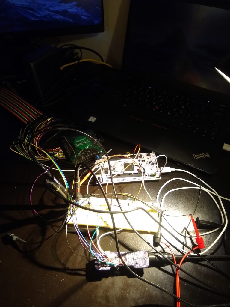
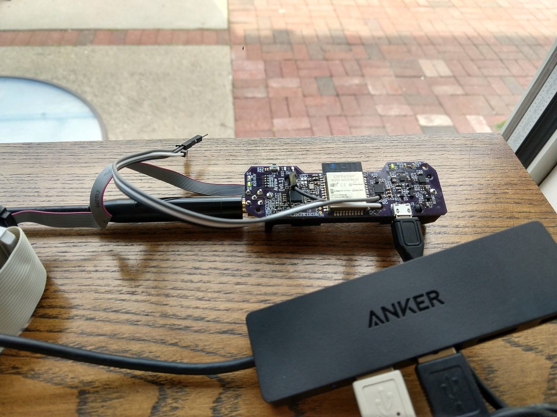
I’m using a STM32 development board strapped to a hacked up Arrow PCBA. The STM32 samples the CFM registers from the CC1200 and dumps the data over USB.
You hear example audio taken from the CC1200 below. Be careful if you’re wearing headphones as there is a bit of static.
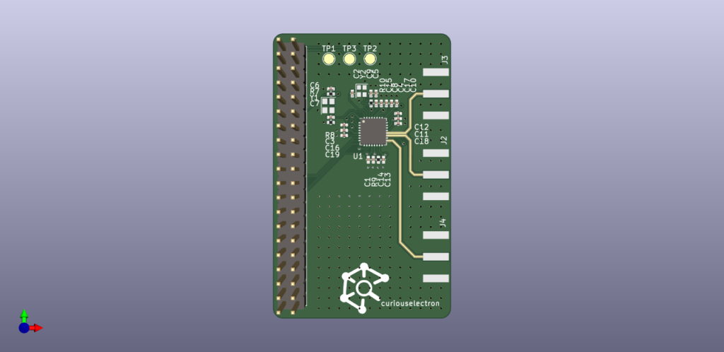
In a quest to measure the input impedance of the CC1200’s LNA in the 2m amatuer radio band, I created a basic development board for the CC1200. The data lines were broken out to a raspberry-pi header, and the RF lines were routed out to edge mount SMA connectors via 50Ohm microstrip. The stackup was JLC2313.
Render of CC1200 Development Board.
This design had a number of issues.
JLCPCB offers a calculator which accounts the soldermask. I didn’t use this tool and instead used KiCad’s built-in calculator which doesn’t account for soldermask. To eliminate this variable, I removed solder mask from the RF traces. This is a common practice, but in the future I should make sure to keep soldermask within the courtyard of the CC1200.
I designed the microstrip to use the 7XXX stackup offered by JLCPCB and not 2313 :D, opps.
The PA and LNA traces are different lengths! This means in order to de-embedded the measurements, I need to calculate the phase-delay for each length (assuming the microstrip is actually 50Ohms…it wasn’t) or perform additional measurements to de-embedded.
The SMA footprint is poorly matched, but to be frank – I wasn’t completely sure of this at this time.
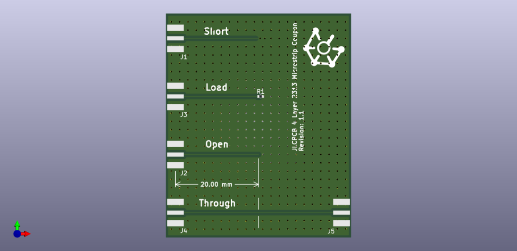
In light of all these issues, I decided to run back to basics and create a basic coupon based on the JLC2313 stackup using the JLCPCB calculator. The coupon was designed to used as a SOL cal standard for de-embedding a 20mm microstrip trace. A 40mm microstrip through connection was also added to quickly confirm the performance of the stackup.
Render of SOL calibration standard for 20mm microstrip de-embedding.
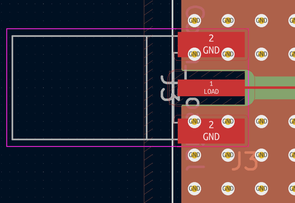
Lastly, after reading a few papers on proper signal launch and reviewing data from the defunked CC1200 development board, I decided to order two versions of the coupon with different versions of the SMA footprint. Both are optimized to have the smallest possible center pin pad, but version v1.0 has ground underneath the center pin, and version v1.1 has a keepout for all copper under the center pin.
Close up of SMA footprint with ground removed from center pin.
Removal of copper under the center pin was critical to achieving an excellent match. The data below was collected using the NanoVNA V2.4 using the curiousmeasurements python package.
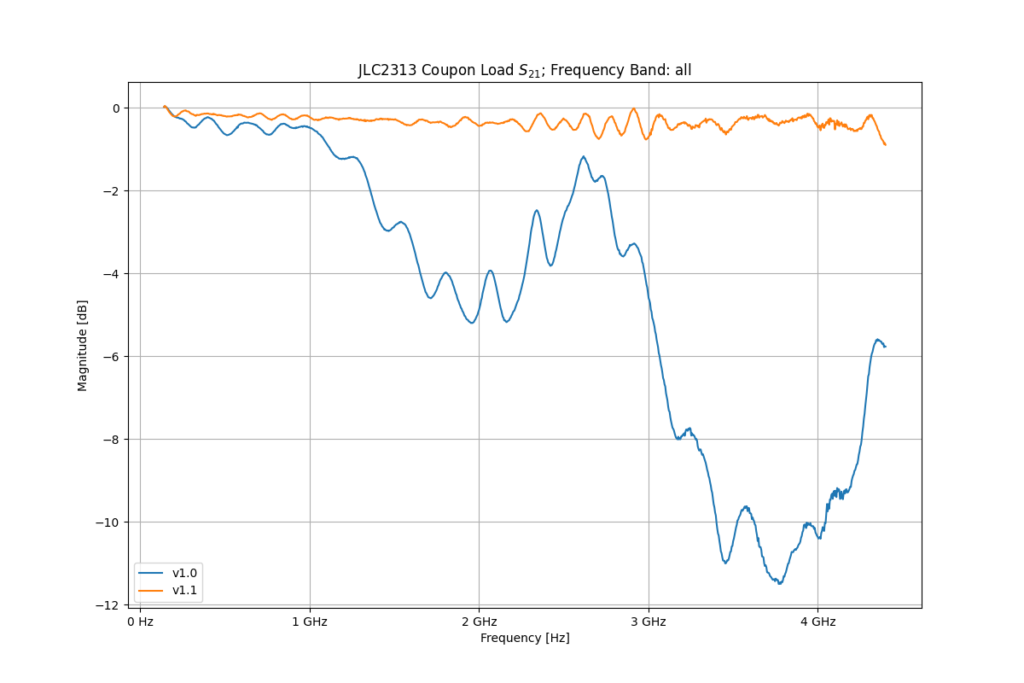
S11 and S21 Measurements from v1.0 (no keepout) and v1.1 (keepout under center pin) revisions.
Version v1.0’s match is unusable above 1GHz, while v1.1 has a return loss <-10dB all the way to 4.4GHz. Not bad for some no-name Amazon SMA connectors…
The same continues for transfer response. The performance is excellent for v1.1. I was quite surprised how much such a small change drastically improved performance.
I’ve been working on Arrow for a while now, but I think it’s time I put it to rest for a bit and write down what has been completed.
I’ve learned lots of fun things from this project (and some horrible things…like AX.25 and the FCC limitations on the 2M band’s data rates!) and I hope someone in the future can make use of it or would be willing to work with me to encourage further development!
What is It?
Currently, Arrow is a full fledged TNC which means the following KISS parameters are supported: TX Delay, TX Tail (why is this even a thiiiiing?!?), Slot Time, and Persistence with built-in BLE connectivity and a 2M radio which is frequency agile. In addition to AFSK for AX.25, the radio supports FSK, GFSK, MFSK, and OOK along with M-ary options.
What is a TNC?
TNC for the uninformed stands for Terminal Node Controller in the amateur radio space….Yeah, I didn’t get much from that the first time I heard it either. In fact, I still don’t. I recommend reading the Wikipedia page for a primer.
In short, a TNC is a modem which was used in the early days of packet radio (actually lives on today mainly in APRS) to send digital data from your computer over audio links. TNCs were fantastic because they allow anyone with a radio capable of sending audio (the most common kind when TNCs were all the rage) to send digital data. You can think of it as the cooler cousin of your 56K dial-up modem, but typically way slower.
TNCs were originally used around about the same time the internet was in it’s infancy. The infrastructure and cost at the time for the internet was substantial; so instead amateur hobbyists would setup internet-like networks using what amounts to their walkie talkies, their home computer, and I hope you can guess it at this point – yes, their TNC.
Why did I do it?
I want to explore and eventually create a new standard for packet radio in the Amatuer space which could provide voice, and data. While I’m still far from the dream I knew the solution would need the following:
Use modern digital modulation techniques for better BER at low SNR.
Reverse compatibility or support of AX.25 for APRS.
Cheap to drive adoption
Built-In Radio and Frequency agile
Current Specifications and Capabilities
Hardware
TI (CC1200) RF Transceiver IC with Balun + Matching Network for 2M (no PA at the moment)
ESP32
18650 cell w/ built-in charger
Micro-USB connection for charging and UART access for debugging
JTAG port
Status LEDs
TX
RX
Battery Charging
Battery Charged
Capabilities
Arrow uses the KISS protocol over the Bluetooth SPP profile. This means when Arrow is connected to a computer, tablet or phone it presents itself as a virtual serial port. The KISS protocol is one of the standardized methods used to communicate and configure TNCs; therefore, it is well supported by existing programs (LinBPQ), apps (APRSDroid), and kissattach (Linux’s ax25-tools).
The uC on-board (ESP32) directly samples data from the CC1200 to decode FM AFSK BELL202 utilized for the standard 1200bps AX.25 used for APRS. Here you can see a video using two arrows to send a ping request over AX.25.
This combination provides what amounts to a plug-and-play solution for linking Arrow into existing Amatuer Radio solutions. The combination does have some limitations I hope to address (see below), but I believe hits most of my goals listed above.
Limitations
The current implementation has the following limitations:
The CC1200 does not support LoRa or PSK.
The output power is very low (+15dBm) and a PA must be added for this to be viable solutions. Please reach out to me if you’re willing to help.
Bluetooth SPP is not supported by iOS, but luckily the code can be adjusted to use a BLE GATT/GAP setup instead.
Learn More
Here is a presentation I’ve done on Arrow
Where can I get one?
I don’t believe the current solution is viable with its low output power. It does work well as an APRS receiver. If you’re interested in purchasing one feel free to contact me via this forum. The code and electrical design files can be found here. Hack away.